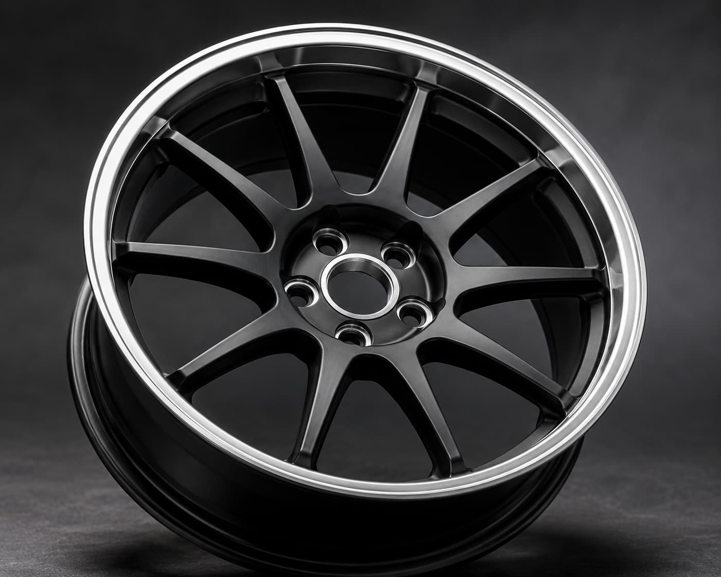
PCD, ET (offset) and center bore are the three numbers that decide whether a wheel physically fits a vehicle: PCD is the diameter of the imaginary circle running through the centers of the bolt holes, ET is the distance in millimetres from the wheel’s hub mounting face to the wheel’s centerline, and center bore is the diameter of the hole that seats the wheel on the vehicle hub. Get any one of them wrong and the wheel either will not bolt on, will foul the caliper or fender, or will vibrate at speed. For a custom forged order these three values are not optional detail — they are the order.
The Short Answer (TL;DR)
- PCD (bolt pattern) — written as number of bolts × circle diameter, e.g. 5×112. Must match the hub exactly. 5×112 and 5×114.3 are only 2.3 mm apart and are the single most common ordering mistake.
- ET / offset — millimetres from mounting face to wheel centerline. Higher ET pulls the wheel inboard (toward strut and caliper); lower ET pushes it outboard (toward the fender). 1 mm of ET = 1 mm of lateral movement.
- Center bore (CB) — the hub-locating hole. A hub-centric wheel carries vehicle load on this bore, not on the studs. Bored too small it will not mount; bored too large without a ring it can vibrate.
- Lug seat type — the fourth spec buyers forget. Conical (60°), ball/radius, and flat-seat with bolts are not interchangeable.
- For a quote we need: diameter × width, PCD, ET, center bore, lug seat type, quantity, destination port.
PCD (Bolt Pattern): What the Two Numbers Mean
PCD stands for Pitch Circle Diameter. A pattern written as 5×112 means five bolt holes evenly spaced on a circle 112 mm in diameter. The first number is the bolt count; the second is that circle’s diameter in millimetres (occasionally in inches on older American applications, e.g. 5×4.5″ = 5×114.3).
How to Measure PCD Without the OEM Sheet
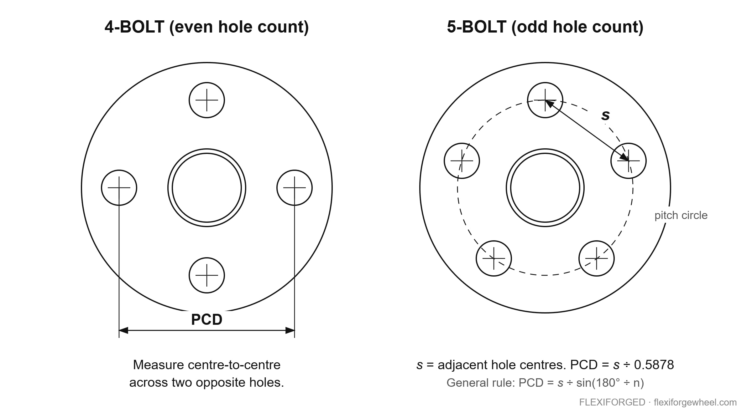
With an even bolt count, measure center-to-center between two directly opposite holes — that distance is the PCD. With an odd count (typically 5), there is no opposite hole, so use the chord formula:
PCD = s ÷ sin(180° ÷ n)
where s is the center-to-center distance between two adjacent holes and n is the bolt count. For a 5-bolt wheel that is s ÷ 0.5878 — an adjacent spacing of 67.2 mm gives 114.3 mm. The workshop shortcut (measure from the center of one hole to the far edge of the hole two positions away) gets you close but is approximate; on a 2 mm decision it is not close enough.
Common Patterns You Will See in Wholesale Demand
| PCD | Typical vehicle families | Watch out for |
|---|---|---|
| 5×112 | VW/Audi group, Mercedes-Benz, newer BMW | Easily confused with 5×114.3 |
| 5×114.3 | Japanese and Korean sedans/SUVs, Ford Mustang | Center bore varies widely inside this group |
| 5×120 | Older BMW, some GM and Land Rover | Ball-seat vs conical seat differences |
| 5×130 | Porsche, Mercedes vans, some VW | High load ratings often specified |
| 5×100 | Subaru, older VW/Audi, Toyota compacts | Small brake clearance envelope |
| 6×139.7 | Pickups and body-on-frame SUVs | Higher load rating and thicker hub face |
Reference only — always confirm the pattern against the specific vehicle year and trim before releasing a drawing to production.
A Note on Dual-Drilled (“Multi-Fit”) Wheels
Two patterns drilled into one hub face is possible, but it removes material from the highest-stress area of the wheel and complicates load rating and third-party testing. For forged monoblock production we recommend a single, correct pattern per SKU. If your inventory strategy genuinely needs multi-fit, send us the two patterns and the intended load rating first so we can review it at the drawing stage rather than after tooling.
ET / Offset: Where the Wheel Sits in the Arch
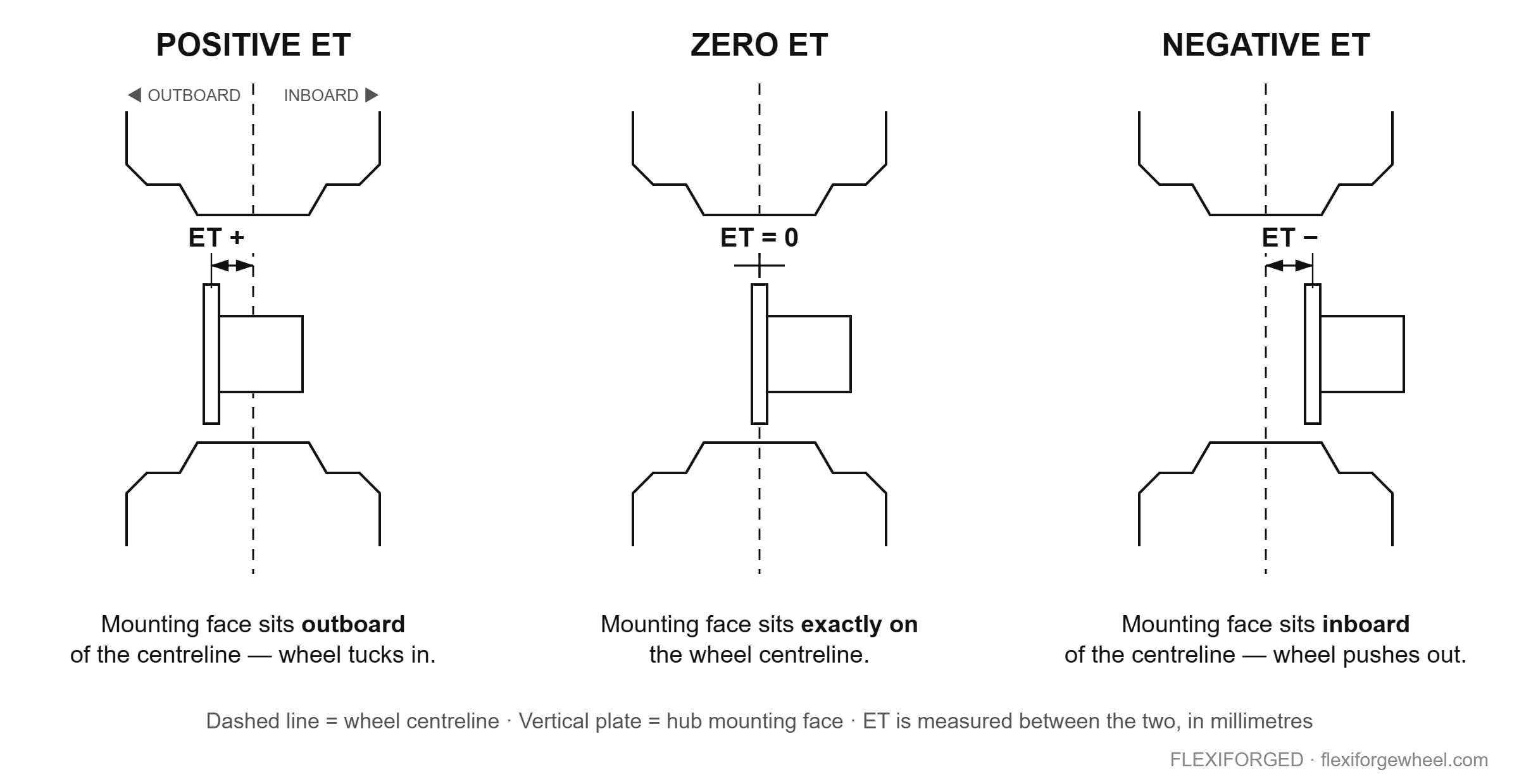
ET comes from the German Einpresstiefe — insertion depth. It is measured in millimetres from the wheel’s hub mounting face to the true centerline of the rim width.
- Positive ET — mounting face sits outboard of centerline; the wheel tucks into the arch. Standard on most modern front-wheel-drive and European platforms.
- Zero ET — mounting face is exactly on the centerline.
- Negative ET — mounting face sits inboard; the wheel pushes out past the fender. Common on deep dish and off-road builds.
The Arithmetic Buyers Actually Need
| Change | Result at the wheel | First thing it hits |
|---|---|---|
| ET reduced by 10 mm (same width) | Wheel moves 10 mm outboard | Fender lip, arch liner |
| ET increased by 10 mm (same width) | Wheel moves 10 mm inboard | Strut body, brake caliper, suspension arm |
| Width +1.0″ at unchanged ET | +12.7 mm inboard and +12.7 mm outboard | Both clearances at once |
| Width +1.0″ with ET +12.7 mm | Inner edge unchanged; all extra width goes outboard | Fender only |
| Width +1.0″ with ET −12.7 mm | Outer face unchanged; extra width goes inboard | Caliper and strut clearance |
Backspacing is the same information expressed from the inner rim edge instead of the centerline. Approximate conversion: backspacing (mm) ≈ ET + (rim width in mm + 25.4) ÷ 2, where the 25.4 mm allows roughly half an inch of flange per side. Nominal rim width is measured bead seat to bead seat, so overall width is always greater than the J number on the label — a detail that catches out buyers converting between US and European spec sheets.
Center Bore: The Spec That Causes Vibration Complaints
Center bore is the diameter of the machined hole in the middle of the wheel that slides over the hub’s locating spigot. On a hub-centric setup the bore and spigot carry the vertical load and locate the wheel concentrically; the bolts then supply clamping force. On a lug-centric setup the tapered lug seats do the centering. Almost all modern OEM applications are hub-centric, and vibration complaints from an aftermarket wheel are very often a bore that was left oversize.
| Bore condition | What happens | Fix |
|---|---|---|
| Bore = hub spigot (hub-centric) | Wheel self-centers; load path through the bore | Correct — specify this |
| Bore smaller than spigot | Wheel will not seat flat against the hub face | Cannot be corrected in the field — remake |
| Bore larger, no ring | Wheel centers on the lugs only; steering vibration is common | Hub-centric ring, or bore to spec |
| Bore larger + correct ring | Acceptable; ring quality and fit determine the result | Use alloy rings for multi-vehicle stock |
Widely published OEM bores include roughly 57.1 mm on many VW/Audi models, 66.6 mm on Mercedes-Benz and some Audi, 72.5–72.6 mm on BMW, 60.1 mm on Toyota/Lexus, 64.1 mm on Honda and 66.1 mm on Nissan — but treat those as a starting point, not a spec. Bores change between generations and drivetrain variants, so confirm the figure for the exact vehicle before we cut metal.
Don’t Forget the Lug Seat
Conical 60°, ball/radius and flat seat with a separate bolt are three different geometries. Fitting a conical nut into a ball seat contacts on a line instead of a face, loses clamp load and can loosen. Tell us which seat type you need in the same message as your PCD; it is machined at the same stage.
How These Specs Affect Cost, Lead Time and Compliance
- Cost. PCD, ET and bore are machining parameters on a forged blank, not separate tooling, so a fitment change inside a size family rarely changes the unit price. Diameter, width and construction (monoblock vs multi-piece) are what move cost.
- Lead time. Because these are CNC parameters, a new fitment on an existing design usually runs on standard lead time. Our published lead times run from drawing approval, in calendar days: samples 10–15, monoblock 25–30, 2-piece 35–40, 3-piece 40–45.
- Compliance. Third-party approval schemes test a wheel in a defined configuration. Change the ET or width materially and you are outside the tested configuration. If your market needs a test report, freeze the fitment before testing starts.
Mandatory vs Optional by Market
| Market | Typically required for road use | Commonly voluntary |
|---|---|---|
| EU / Germany | ECE R124 approval for replacement passenger-car wheels; German registration often expects a TÜV part report | Additional brand-specific testing |
| Japan | JWL marking | VIA registration |
| North America | No federal aftermarket wheel approval scheme | SAE J2530 performance testing, widely requested by buyers |
| Australia | Vehicle must remain ADR-compliant after modification; state rules apply | Independent test reports for engineering sign-off |
| South Africa | Generally aligned with ECE practice | Buyer-requested third-party reports |
Regulatory summary for orientation only — confirm current requirements with your local approval authority or importer before committing to a program.
How FLEXIFORGED Handles Fitment
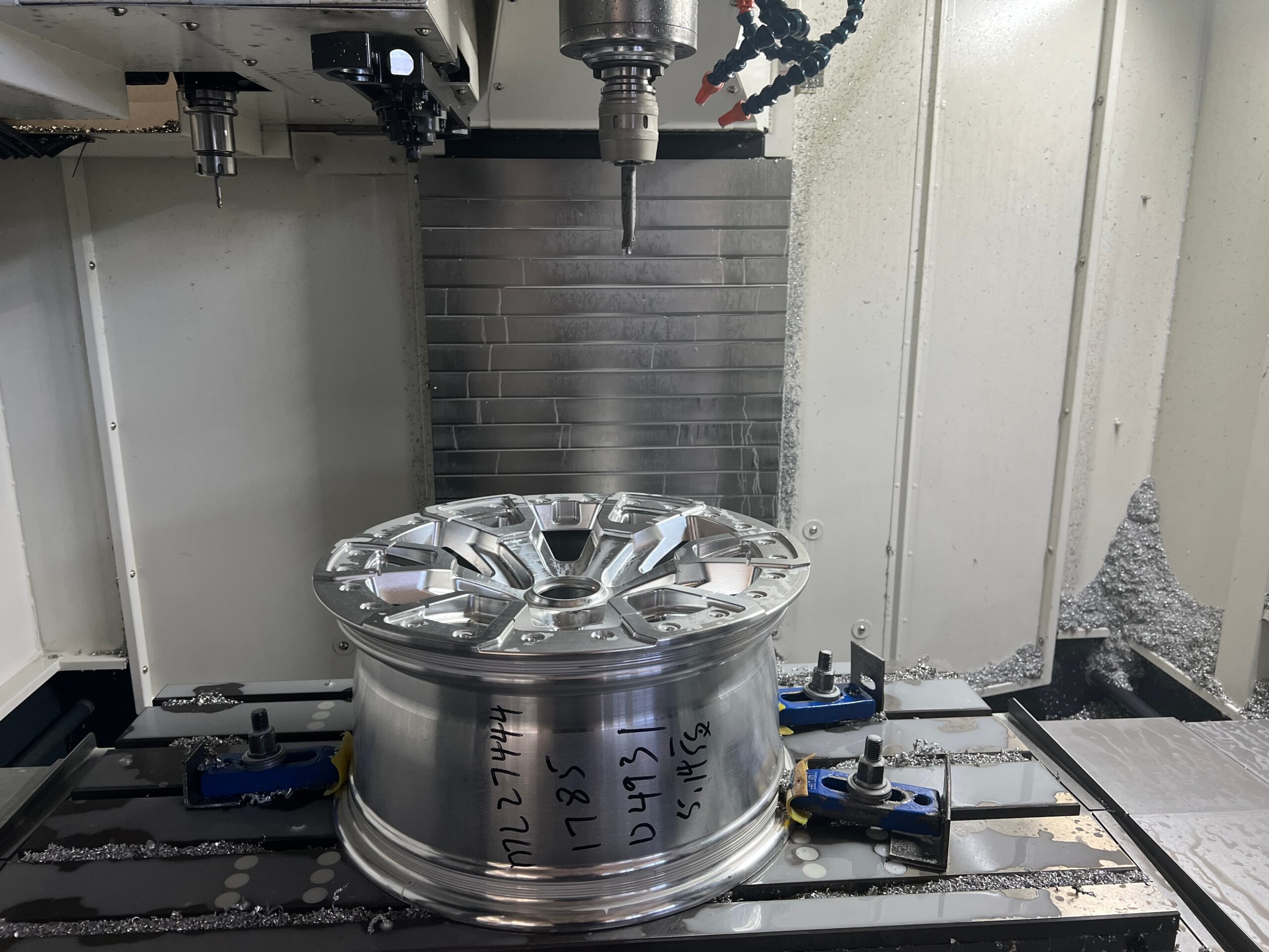
FlexiTech International LLC has operated the FLEXIFORGED line from Chongqing, China since 2017 as a factory-direct manufacturer, not a trading company. Forging and finish machining happen in-house across 60+ CNC machines (3-, 4- and 5-axis), which is why fitment parameters are handled as production data rather than as a request passed down a supply chain.
- Drawing first. Every order is confirmed on a drawing showing PCD, ET, center bore, lug seat, disc thickness and load rating before machining starts. Nothing is cut on an email thread alone.
- Bore machined to your figure. We machine the center bore to the hub dimension you specify rather than defaulting to an oversize bore plus rings.
- Materials. 6061-T6 aluminium as standard, AZ80 and ZK60 magnesium where weight targets justify it.
- Quality system. ISO and IATF certified. Third-party TÜV or SGS testing can be arranged on request when your market or your customer needs a report.
- Order flexibility. MOQ is 4 pcs per design and mixed sizes are allowed, so staggered front/rear fitments do not force separate orders.
If you are still deciding between constructions before you lock a fitment, our forged monoblock wheels page covers the one-piece option, while forged 2-piece wheels gives you adjustable barrel widths — useful when a customer’s ET requirement sits between standard values. The full range and process sit on the custom forged wheels hub.
Frequently Asked Questions
How do I measure PCD if I don’t have the OEM spec?
For an even bolt count, measure center-to-center between two directly opposite holes — that figure is the PCD. For 5-bolt wheels, measure center-to-center between two adjacent holes and divide by 0.5878. A 67.2 mm adjacent spacing gives 114.3 mm. Send us the raw measurement if you are unsure and we will confirm the standard pattern it corresponds to.
Can you make one wheel fit two different bolt patterns?
Dual drilling is technically possible but it removes material from the highest-stress part of the hub face and complicates load rating and third-party testing. For forged wheels we recommend one correct pattern per SKU. If multi-fit is essential to your stocking plan, send both patterns and the target load rating so we can review it before tooling.
What ET should I order if I go one inch wider?
An extra inch of width adds 12.7 mm on each side if ET stays the same. To keep the inner clearance untouched and push all the extra width outboard, increase ET by 12.7 mm. To keep the outer face where it was, decrease ET by 12.7 mm. Which direction is right depends on whether the tight clearance is at the caliper or the fender.
Do you machine the center bore to my exact hub size, or do I use spacer rings?
We machine the bore to the figure you give us, so hub-centric fitment is achieved in the wheel itself. Rings are a reasonable option when one SKU has to cover several vehicles in your stock, but for a vehicle-specific order a machined bore is the cleaner solution and avoids vibration complaints downstream.
Are your wheels tested to JWL, VIA or TÜV standards?
Production runs in an ISO and IATF certified facility, and third-party testing through TÜV or SGS can be arranged on request. Tell us which market the wheels are going to and which approval your customer or importer requires, and we will scope the testing against that specific fitment before production starts.
What do you need from me to quote a custom fitment?
Diameter × width, PCD, ET, center bore, lug seat type, quantity per design and your destination port. If you have OEM data or a photo of the existing wheel’s back face, include it. We quote EXW, FOB or CIF and ship under HS code 8708.70.
Get Your Fitment Quoted
Send the six lines below and you will get a drawing-level answer rather than a generic price list. MOQ is 4 pcs per design, mixed sizes allowed.
Size × Width · PCD · ET · Quantity · Destination port · Email
Email Jackie Wei, Co-Founder: jackie.wei@flexiforged.com